

It is recommended that your analyzer be checked for accuracy on an annual basis. If your calibration is off or is reading incorrectly, then follow the steps below for recalibration. To verify the accuracy of your analyzer, simply connect the sample line to a cannister of known test gas and ensure that the reading on your controller screen matches the test gas. Quotes for test gas can be requested via support@southteksystems911.zendesk.com or (910) 415-1880.
- Turn generator off.
- Close the ball valve connected to sample line at N2 storage tank.
- Disconnect sample line from outside of electrical cabinet.
- From the PLC (display) on the generator:
1.Press “Menu”
2.Enter Password (6557) and press the bottom right button (return key).
3.Select “sensor setup/calibration.”
4.Select “O2 PPM/% calibration”
For % Units:
1.Enter the contents of your known gas source in the field labeled “0-2% O2 Calibration Gas.” This will be listed on the Test Gas cannister and is typically 1%.
2.Enter 20.9% in the field labeled “20-22% O2 Calibration Gas.”
For PPM units:
1.Enter the contents of your highest purity (lower PPM) known gas source in the field labeled “O2 PPM Low Calibration.” This will be listed on the Test Gas cannister and is typically 10 PPM.
2.Enter the contents of your lowest purity (higher PPM) known gas source in the field labeled “800-1000 PPM Cal Gas.” This will be listed on the Test Gas cannister and is typically 700 PPM.
3.Connect the provided regulator onto your higher purity (10 PPM) known gas source.
4.Connect the provided tubing over the sample line connector on the electrical cabinet.
5.Open the valve on the regulator and allow gas to flow to the analyzer for minimum of 5 minutes.
6.On the PLC there is a value displayed at the bottom of the calibration screen labeled “Current Raw”.
7.Take the “current raw” value and enter it in the top field (low side calibration)
8.Close the valve on the regulator.
9.Switch the regulator to your high side calibration gas.
10.Open the valve and allow gas to flow for 5 minutes.
11.On the PLC there is a value displayed at the bottom of the calibration screen labeled “Current Raw”.
12.Take the “current raw” value and plug in the 2nd field (high side calibration)
13.Close the valve on the regulator.
14.Disconnect the tubing from the sample port.
15.Reconnect your sample line to the sample port.
16.Open the valve on the storage tank feeding the sample line.
This should complete calibration on your analyzer. If you have trouble or require assistance, please give us a call at 910-415-1880.
Fire Protection
N2-Blast Filter Kit
| FPS-250, 250FF, 500, 750, 750FF, 900, 1650 | FRP-007 |
| FPS-1750, 3000, 6000 | FRP-002 |
| FPS-12000, 15000, 18000, 20000, 22500 | FRP-006 |
| FPS-3250, 5000, 10000 (BLACK FILTER BOWLS) | FRP-013 |
| FPS-3250, 5000, 10000 (WHITE FILTER BOWLS) | FRP-022 |
| POWER SAVER MANIFOLD | 100692 |
| QUICK CHECK PURITY MANIFOLD | 100692 |
MIC Blast Filter Kit
| FPS-20, 50 | FRP-007 |
| FPS-125, 200, 400 | FRP-002 |
| FPS-2000, 3000 | FRP-006 |
Beverage
| 1KPH, 3KPH, 7KPH, 14KPH | FRP-001 |
| 100, 200 | FRP-003 |
| 400 | FRP-004 |
| 100, 200, 400 PLUS | FRP-001 |
| 600, 800 PLUS | FRP-005 |
Labtek
| 35L, 30D | FRP-015 |
| 70T | FRP-017 |
| 70L, 90D | FRP-016 |
Tire Blast
| NT-10, NT-20, NT-40 | FRP-009 |
| NT-130, NT-250 | FRP-008 |
Transmissions Lines
| TL-450, TL-1050, TL-1825 | FRP-007 |
| TL-1725, TL-2625 | FRP-010 |
Please reach out to the email or phone number below for quotes on any of the above, or if you do not see your particular N2 generator listed.
support@southteksystems911.zendesk.com
910-415-1880
- Systems are warrantied against any defects in workmanship and materials for 12 months (or 1000 hours) from the date of shipment unless an extended warranty was purchased.
- The purchaser has the liability to ensure that the system is fully inspected upon delivery and shall contact the appropriate shipping company to make any claims on damaged goods due to transit within that shipping company’s policies.
- If the system is received with defects that are not due to shipping, a claim should be submitted
to South-Tek Systems within 1 week of receiving the shipment. South-Tek Systems can deny all
other claims at their discretion. - Any work performed by an unauthorized person/company or usage of non-factory parts
may void all warranties to the product. - Any item not manufactured by South-Tek i.e., external compressors, may carry its own warranty from its manufacturer and will be warrantied by that manufacturer.
- All parts that need to be returned should be announced. Any item(s) that is returned to South-Tek Systems without an RMA number (return authorization number) may be denied and returned to the sender.
- Contact the factory for RMA #’s, prior to return shipment. South-Tek Systems is not liable for damages caused by normal wear and tear, water, fire, erosion, corrosion, explosion, misuse, oil/gas vapors or unauthorized modifications. South-Tek Systems is also not liable for any losses (including CO2), damages, or cost of delays, including incidental or consequential damages. There are no warranties or guarantees, expressed or implied, including the warranties of merchantability or fitness for a particular purpose or use, other than those warranties expressed herein.
- Power down the unit and confirm that the pressure reading on the gauge above the filters reads 0 PSI.
- Disconnect the drain lines from the filter bowls by pushing the orange rings towards the filter bowl, while pulling down on the poly lines.
- Unscrew the filter bowls by hand by rotating the outer metal casing clockwise.
- Pull down on the plastic filter bowls to remove them from the upper filter housing taking care to remove the O-rings. The O-rings can be discarded.
- The black filter element on the left can be removed from the upper filter housing by rotating clockwise and discarded.
- The white filter element on the right can be removed from the plastic filter bowl by gently prying up on the black upper filter assembly with the O-ring removed. Once removed from the filter bowl, rotate the lower piece of the filter assembly a quarter turn counter clockwise. The white element can be discarded and replaced and then reassembled.
- Fill the plastic filter bowl about half way with warm soapy water and shake with your hand covering the top opening. Repeat for both bowls. This will ensure that the float drain is clean and operational.
- Remove and replace the O-rings on the lip of the plastic filter bowl.
- Install the outer metal casing back onto the plastic filter bowl, taking care to line up the protrusion on the bottom with the opening in the metal casing.
- Reinstall the filter housing and casing back into the upper filter assembly. Only tighten hand tight and do not use a wrench.
- Reinstall the poly drain lines by pushing up into the bowl until the push to connect fitting locks the line into place.
- The compressor intake filter can be replaced by pushing down on the black filter bowl located on the top of the compressor and rotating counter clockwise. Take care that the filter housing may be hot.
- Turn on the unit and test for any leaks with a a spray bottle and soapy water.
- Reset the filter alarm by holding the Down (-) key on the controller for 10-15 seconds.
APS devices should be installed at the end of each zone, as far from the generator as reasonably possible. You will want to ensure that they are accessible to adjust the purge rate and take purity samples when needed.
It is important that the APS ball valve be closed anytime water is introduced to the zone to prevent the purge from getting clogged.
See attached Field Tuning Guide to correctly set the purge amount.
A full list of O&M manuals, GA drawings, and electrical schematics can be found at southteksystems.com for most of our current line of products. Simply hover your mouse over the respective market you are searching for and look for your model. All documentation will be found under the “documents” column. If you need documentation on legacy products or additional support, please Contact Us.
Commercial
FPS-500
FPS-900
FPS-1650, FPS-3250, FPS-5000
FPS-10000, FPS-16500, FPS-22500
_______________________________________________________________________________________________________________________________
- Pressurize the system while isolating it by closing the valves from your N2 storage tank to your end process as well as any sample lines going back to the cabinet analyzer (if present).
- The system should build pressure until the unit reaches standby. Cut in/out pressures can be found here: What Are My Cut In/Out Pressures?
- Once the unit reaches standby, monitor the tank pressure, this should remain static and not drop.
- If tank pressure is dropping or the system struggles to reach stand by, spray any fittings or filter bowls with soapy water looking for bubbles. Take care to avoid any electrical components inside the cabinet while leak testing.
- If a leak is detected on a fitting, tighten NPT fittings, or reseal push to connect fittings by pushing the poly line towards the fitting to see if leak is sealed. For NPT fittings, additional pipe tape may be required. For push to connect fittings, simply cutting the end of the poly line by a few centimeters and reinstalling may resolve the issue.
- If the leak is unable to be repaired or additional support is needed, please contact us.
- Turn the unit off and back on to clear the alarm.
- Isolate the N2 tank either at the N2 out or at your AMD.
- The unit should fill the tank and go into standby.
- If not, start by making sure your inbound pressure is around 105 PSI at the swing (PSA) or 100 PSI for membrane units. Make adjustments to the regulator, if need be, to reach these setpoints.
- Once unit has reached 105 at the swing, let the unit run to see if it goes into “standby” mode.
- If not, please see the following article to leak test: What is the best way to test for leaks? (zendesk.com)
- If you still need support, please call the service line at 910-415-1880.
BEVERAGE
XX-040PPH – 60/85
XX-01KPH – 70/75
XX-03KPH – 70/75
XX-07KPH – 70/75
XX-14KPH – 70/75
FIRE PROTECTION
FPS-00500 – 55/65
FPS-00650 – 55/65
FPS-00900 – 55/65
FPS-01250 – 55/65
FPS-01250-P-A – 60/70
FPS-03250-P-A – 60/100
FPS-05000-P-A – 60/100
FPS-10000-P-A – 60/100
FPS-16500-P-A – 60/100
FPS-22500-P-A – 60/100
Our industrial units are factory set based on customer needs, and therefore vary from system to system. To find your specific cut in/cut out specifications, please call or email us @ (910) 415-1880, support@southteksystems911.zendesk.com
The User Password for all South-Tek units is 6557. To access Factory Settings, please Contact Us.
- Hold or press the green power button on the display until it turns red.
- Navigate to the Menu on the PLC.
- Go to the maintenance menu.
- Go to valve controls.
- From here you can manually actuate the bypass valve or any valve in the cabinet. Leave the bypass active or in the on position to bypass the generator.
The following models utilize auto-bypass: FPS-1650, FPS-3250, FPS-5000, FPS-10000, FPS-16500, and FPS-22500
*Before starting Contact Us to verify unit’s parameters are on file.
- Insert the Micro SD card supplied by South Tek Systems into the PLC until it locks into place (Micro SD port is located on the top right side of the PLC when looking at the screen of the controller).
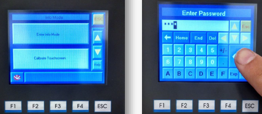
- Hold a blank part of the touch screen for 6 seconds until the screen below is displayed.
- Press Enter Info Mode and the controller will prompt for a passcode. Type “1111” and press enter
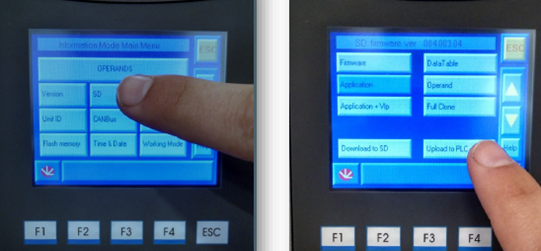
After the passcode is typed in correctly, the screen below will display. Press the “SD” menu button to get to the screen on the right.
- Select application and press upload to PLC.
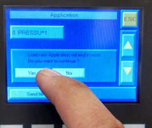
- In the Application screen, select the program and press Send File. Press Yes in the prompt to continue the upload only if it is safe to reset the PLC.
- If there are no programs displaying or more than one program displaying on the Application screen, Contact Us.
Once the program is uploaded the screen may say fatal error until the PLC is initialized.
- Hold your finger down on the PLC touchscreen until you enter info mode.
- Press enter info mode
- Enter the password – 1111
- Press Working Mode
- Press Init on bottom right of the screen
- Press yes
Once initialized you will need to re-enter your unit parameters. For assistance please Contact Us.
Analyzers should be verified annually with a known test gas. These come in various types, 10PPM, 100PPM, 1%, etc. The type needed for your unit will depend on the analyzer and purity specification of your system. The test gas will come in a 1 liter pressurized cylinder that typically lasts a few years. Additionally a special regulator is required to connect the gas to the sample line of your generator. Once the test gas is connected to the sample line, simply open the regulator to allow air to flow. Wait 10 minutes and verify that the reading on your PLC display matches the test gas purity. If so, remove the test gas and continue operating your system. If there is a discrepancy, your fuel cell needs to be replaced. Please Contact Us to get quotes for test gas or if you need further assistance.
CMS levels in your sieve beds should be measured every 18-24 months to check for loss of material and settling. Symptoms of a loss in CMS material include purity not in spec, as well as CMS “dusting” in the process valves and downstream filtration.
To check CMS levels:
- Turn your unit off.
- Valve your N2 storage tank by closing the valve coming from the generator.
- Depressurize your sieve beds by opening the ball valves located on the front of the unit (each side).
- They have yellow handles and have a pressure gauge located next to them. These will stay open for the entirety of this process. Smaller units will not have valves and pressure can be released by pulling up on the safety relief valve on the top of the bed.
- Remove the plugs on the very top of the sieve beds.
- Measure from the top of the threads until your tape measure stops.
- Anything over 7 inches is open void and needs to be topped off. Please Contact Us to get a quote for additional CMS material.